Thread and End Connection Identification

When using any type of hose or tubing, a leak-proof seal is accomplished by properly identifying the type of thread being used. There are 4 primary different seal types when identifying connections: the thread interface, the O-Ring, the mated angle or mechanical joint, and the mated angle with an O-Ring.
Thread Interface
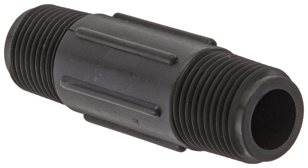
A thread interface type of sealing is characterized by the “male” side being thinner at the front than it is at the back; at least in the tapered variation, of which the most common is NPT (National Pipe Tapered). The reason the pipe is tapered is that it makes it easier to begin threading the male into the female fitting. The tapered thread gets wider as the male is threaded into the female and the edges of the thread distort by flattening out. This distortion creates the seal. Keep in mind that in order to improve the seal, you will need to put Teflon tape on the male end or use a thread sealant paste. This is important because with enough pressure it’s still possible to get leakage because the connection is a helix that can allow for a leak path.
O-Rings
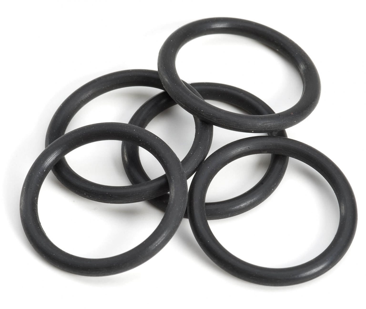
In terms of O-Rings, there are different variations of how the connections seal. The O-Ring on the Male O-Ring Boss fitting sits at the base of the male threads and it mates into a machined groove on the corresponding female. When fully threaded together a hex nut and flat washer on the male are then tightened down against the backside of the O-ring, compressing it and creating the seal.
The Flat-Face-O-Ring is a threaded connection in which the O-Ring goes into a machine groove on the nose of the male end. As the female nut is screwed onto the male threads, it draws the seat of the female – which is a flat surface – and the nose together. The threads pull the fitting against the flat face of the female seat surface, trapping the O-Ring and flattening it to form a tight seal.
The Flange O-Ring is excellent for high-pressure applications. This O-Ring goes into the face end of threadless Flange surface. As the Flange face is pushed against the receiving plate face, bolts are run through locking clamps called “flange-halves” that align the faces, compress the O-Ring, and create the seal.
Mated Angle and Mechanical Joint
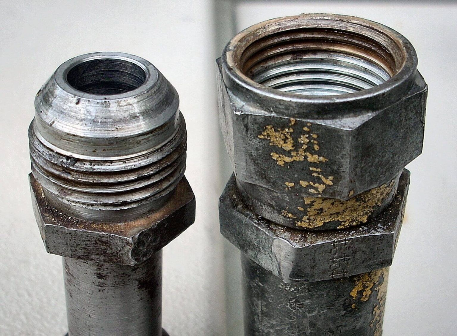
When it comes to a Mated Angle or a Mechanical Joint, matching angles from corresponding male and female fittings are used to create the seal. The angle on the male end is going to match up with the angle in the female seat. As the threads draw the male end into the female seat and get to the proper torque spec, it’s going to create a seal between the two.
The angle can either be forward facing, as present on a JIC male, or with the male angle reverse facing, as in the case of the automotive style Male Inverted Flare. In each type the female connection will be angled to match to the male.
Another Mated Angle O-Ring connection is the British Standard Parallel Pipe (BSPP). British Standard Pipe can also come in other configurations including a tapered thread interface design (BSPT) that often gets confused for NPT.
Foreign Thread Types
Speaking of British Standard, when it comes to foreign connection types, we’ve got Metric threads, which are measured in millimeters. Deutsche Industrial Norm, a German standard, has common connections D.I.N. Light and D.I.N. Heavy, both measured in millimeters and allow for threaded or tubing style connections.
There are multiple metric fittings in the industrial workplace from the Japanese, French, and European industries including flanges, tubing compression, and O-ring seals.
Identifying Fittings
But what happens when you need to identify fittings and have minimal information? Collecting as many measurements as you can, O.D., if threaded, how many threads per inch there are, etc. is helpful. With that information, you can begin to figure out most any fitting.
For example, let’s say you have a male thread and it has a visible O-Ring at its base, and it is ¾ inch by 16 threads per inch. If we consult the fittings chart at the end of this page, we need to look for an O-Ring that is ¾ inch that also happens to be 16 threads per inch. Once we match up those findings on the chart, we will see that it is a Dash 8 (- 8) Male O-Ring Boss.
Another example would be a fitting that has a 45-degree angle, with 18 threads per inch with 5/8 inch measured outside the diameter. To find what that is, we would once again consult the fittings chart. Knowing that it’s a 45 degree, we see it’s an SAE flared thread. Since it was 5/8 inch with 18 threads per inch, we can identify that it’s doing to be a Dash 6 (-6) Male SAE.

Measuring Fittings
One of the tools that we can use to identify what a thread is, is a thread gauge, which you lay against the male fitting. If the thread gauge aligns with the threads and doesn’t let any daylight through, you have identified the threads per inch. You will also need to know what the outside diameter of the male fitting is.
When it comes to measuring fittings, one area we need to check is the Seat Angle when present. If you measure the outside of the male angle of the cone, that makes it very simple. The tool sits right on the outside of the cone and quickly shows the fit/angle. The 37-degree angle is standard JIC, very common. Also prevalent is the 45-degree angle, which is SAE. A 30-degree angle that is usually reserved for Japanese Industrial Standard fittings can also be encountered.
Identifying flange fittings is done by measuring O.D. and thickness. There are three primary flanges used. Code 61, Code 62, and Caterpillar flange. Code 61 takes pressures up to 3,000 psi working and O.D.’s and thicknesses are unique to it. Code 62 and Caterpillar flanges both work at 6,000 psi. While Code 62 and Caterpillar flange share O.D. dimensions they do not share thicknesses, thus every flange type requires its own, properly mated, set of flange-halves and bolts.
There are also French and Japanese (Kumatsu) flanges out there but less common.
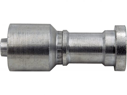
Caterpillar Flange
Differences Between SAE and JIC
Note that when it comes to JIC and SAE, there are an abundance of similarities and only a few critical key differences. JIC threads come in “dash” sizes (represented by a hyphen mark, or ‘dash’) from 1/8”
(-2) thru 3” (-48). SAE threads come in “dash” sizes from 1/8” (-2) thru 3/4” (-12).
The most important difference is that only two sizes of JIC do not thread together with their counterparts in SAE -6 and SAE -12.
In JIC – 6, the O.D. is 9/16 by 18 threads per inch while in SAE – 6 the O.D. is 5/8 inch by 18 threads per inch. The threads per inch are the same, but the O.D.’s are different.
In JIC Dash -12 you have 1 1/16-inch O.D. with 12 threads per inch, while in SAE -12 you have 1 1/16-inch O.D. by 14 threads per inch. In this pairing, the threads per inch are different while the O.D.’s are the same.
In all other thread sizes two, three, four, five, seven, eight, and ten, the threads are fully identical in both SAE and JIC.
That leads us to the only other key difference between JIC and SAE, the angle of the cone that seals the connection. JIC has a 37-degree cone and SAE has a 45-degree cone. While they are technically different modern manufacturing (from companies of good repute) has created a dual-seat system in the female portion of the fittings that allows either male angle to be threaded into it and to seal well against the female. Again, that is true in every size but -6 and -12 as they are not going to thread together at all.
There is a rule-of-thumb that most SAE fittings out there are made of brass and most JIC fittings are made of steel. While it nearly universally true – don’t count on everyone always making their fittings according to the rule-of-thumb! Never be afraid to measure, use the chart, or bring your project to our experts to be sure you’re spared any headaches or leaks.
For more information, contact us.